


How to Wire 12V Accessories to Your Golf Cart Fuse Box
Safely Power 12V Accessories From Your Golf Cart Fuse Box
To wire 12V accessories safely, power a dedicated 12V fuse block through a properly sized switching DC-DC voltage reducer connected to the full 36V, 48V, or 72V battery pack. Install an input fuse close to pack positive, connect the reducer's 12V output to the fuse block, then give each light, USB outlet, radio, horn, or other accessory its own correctly sized fuse and wire.
- Add up the amps required by every 12V accessory.
- Choose a reducer with at least a 1.5x margin above that total load.
- Fuse the reducer input and every 12V branch circuit.
- Use the reducer rather than tapping one battery, which can unbalance the pack.
- Test voltage, polarity, and fuse operation before securing the wiring.
This setup keeps accessory circuits organized and protects the wiring if a fault occurs. Most everyday carts fall in the 10A to 20A accessory range, while carts with larger light bars, powerful audio, or high-draw auxiliary equipment may need a 30A or larger reducer. For example, Extreme Kartz carries the Eco Battery Universal 12V Converter 48V–72V (SKU A-1272), along with 30A and 50A options for higher-demand builds. Eco products are excluded from all promotional codes.
I am Martin Davis, owner of Extreme Kartz, where I work with technicians and manufacturers to help cart owners make reliable upgrades. In this guide to golf cart fuse box & 12V accessory wiring, I will show you how to build a clean, protected system without creating battery-balance or wiring problems.
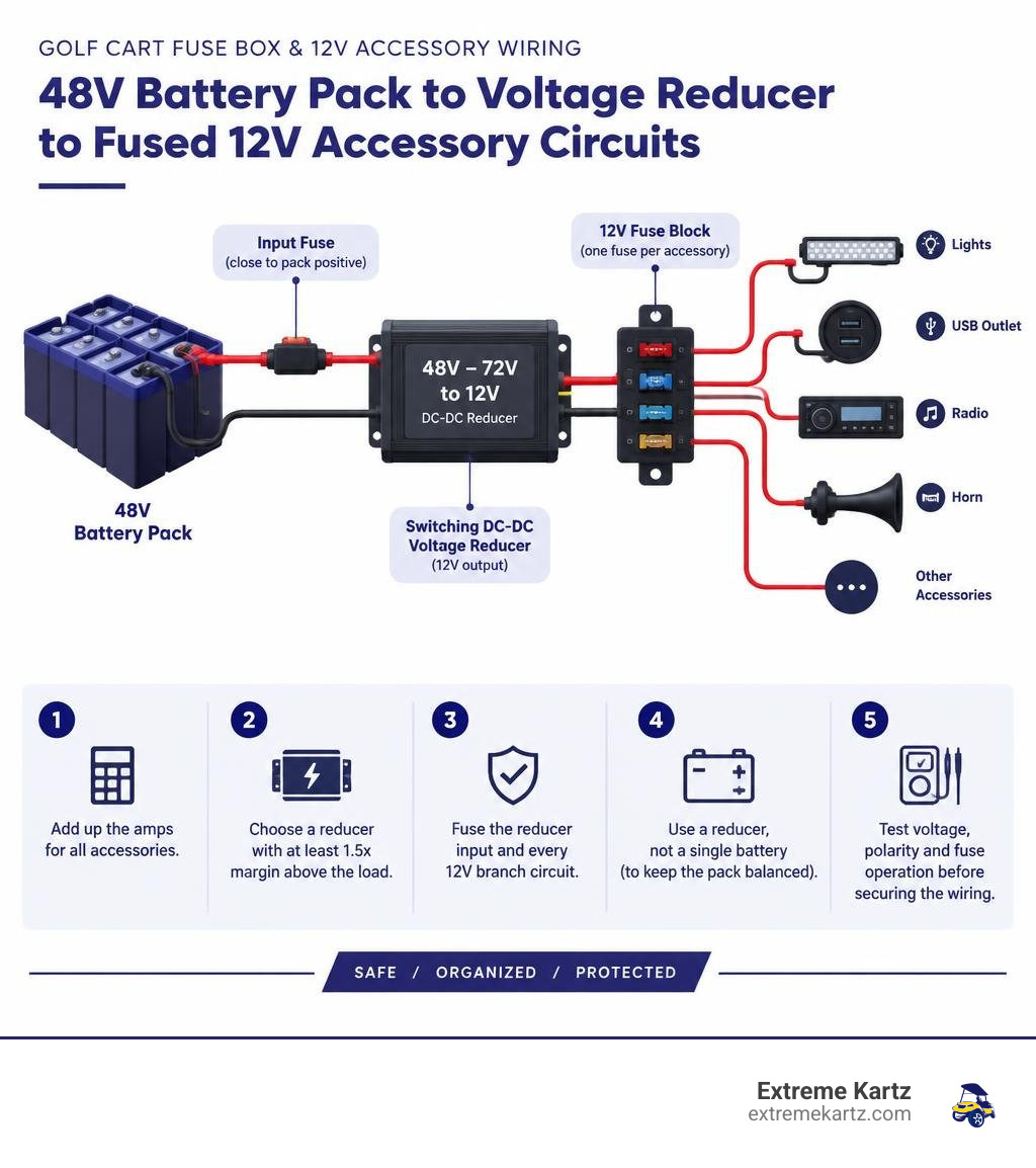
Quick look at golf cart fuse box & 12v accessory wiring:
Understanding Golf Cart Electrical Systems and 12V Power Delivery
Most modern electric golf carts run on 36V, 48V, or 72V traction battery packs designed strictly to feed the motor controller and drivetrain. Standard vehicle accessories—such as LED headlights, turn signals, audio receivers, USB charge ports, and horns—operate on nominal 12V DC power. Connecting standard 12V components directly across high-voltage main terminals results in instant component destruction and serious fire risks.
To bridge this gap safely, we install dedicated voltage reducers. An effective 12V power delivery architecture pulls energy equally across the entire traction battery bank, steps down the voltage efficiently to a regulated 12.0V–13.8V DC output, and directs that power into a central, multi-circuit fuse block. This approach avoids pack balance issues, prevents excessive voltage drop over long wire runs, and gives every accessory a dedicated fuse.
Linear Regulators vs. Switching DC-DC Converters
When choosing hardware to lower high battery voltage down to 12V, the internal technology makes a massive difference in efficiency, safety, and battery longevity.
Linear regulators operate like a variable resistor. They burn off excess electrical voltage as pure heat. On a 48V cart dropping voltage down to 12V, a linear regulator must dump 36 volts of differential. At a moderate 10-amp draw, that equates to 360 watts of wasted thermal energy. Linear units operate at a low 25% to 33% efficiency, which can create excess heat and drain your battery pack quickly.
In contrast, modern switching DC-DC converters utilize high-frequency pulse-width modulation and magnetic inductors to step down voltage with minimal thermal loss. Switching converters achieve 85% to 95% operating efficiency. A typical 12V accessory load drawing 8A (such as an LED light kit, stereo, and USB charger) translates to roughly a 2A draw from a 48V pack when using a switching converter—reducing total cart driving range by only 5% to 10%.
| Specification / Metric | Older Linear Regulators | Modern Switching DC-DC Converters |
|---|---|---|
| Operating Efficiency | 25% – 33% | 85% – 95% |
| Heat Dissipation | High (360W heat waste @ 10A on 48V) | Minimal (Cool-running solid-state design) |
| Impact on Range | Higher battery drain from waste heat | Minimal (Roughly 5%–10% typical range impact) |
| Voltage Regulation | Drifts with pack voltage drop | Tight, stable 12.0V–13.8V DC output |
| Form Factor / Safety | Heavy heatsinks; higher thermal-management demands | Sealed aluminum housings; high IP water ratings |
Extreme Kartz supplies modern, high-efficiency switching units, such as the active Bolt 48V/36V→12V High Output Reducer (SKU 33-006), rated at 30A output with 36V/48V input for approximately $82.95, and the Reliance 30 Amp DC Converter 48/36-12Volts (SKU 13-030), rated at 30A output with 36V/48V input for approximately $85.95. For higher-voltage or heavy-draw builds, we carry the Bolt 50-Amp HD DC/DC 36/72V Reducer (SKU BE-50AMPR72), with 50A output and 36V/72V input, and the Eco Battery Universal 12V Converter 48V–72V (SKU A-1272). For 36V-specific builds, we also stock the Eco Battery 12V Converter for 36V (SKU A-1236).
Why Tapping a Single Battery Fails and Harms Battery Packs
A common shortcut among cart owners is "battery tapping"—connecting 12V accessories across a single 12V battery in a 48V series pack, or across two 6V/8V batteries to draw nominal accessory power.
We strongly advise against battery tapping for several reasons:
- Severe Pack Imbalance: In a series circuit, drawing an extra 10A to 15A off one battery causes uneven discharge. When recharging, standard series chargers read total string voltage and cannot compensate for an individual drained battery.
- Premature Battery Failure: The tapped battery remains chronically undercharged, while the remaining batteries get overcharged. This leads to accelerated sulfation and premature pack failure.
- 16V Tap Hazards: Tapping two 8V batteries on older Club Car Precedent models yields 16V under rest and up to 18V+ under charge, which burns out 12V audio and lighting electronics.
- Lithium BMS Shutdowns: Modern lithium systems rely on balanced cell strings. Tapping an individual cell group bypasses protection, causing early BMS low-voltage cutoffs.
Always pull accessory power evenly across your entire traction pack using a dedicated DC-DC converter.
Complete Guide to Golf Cart Fuse Box & 12V Accessory Wiring
A dedicated multi-circuit, marine-grade fuse block serves as the central power distribution hub for your cart. Rather than cluttering battery terminals with multiple inline fuse holders, a centralized fuse box provides clean wire routing, robust circuit isolation, and quick diagnostic access.
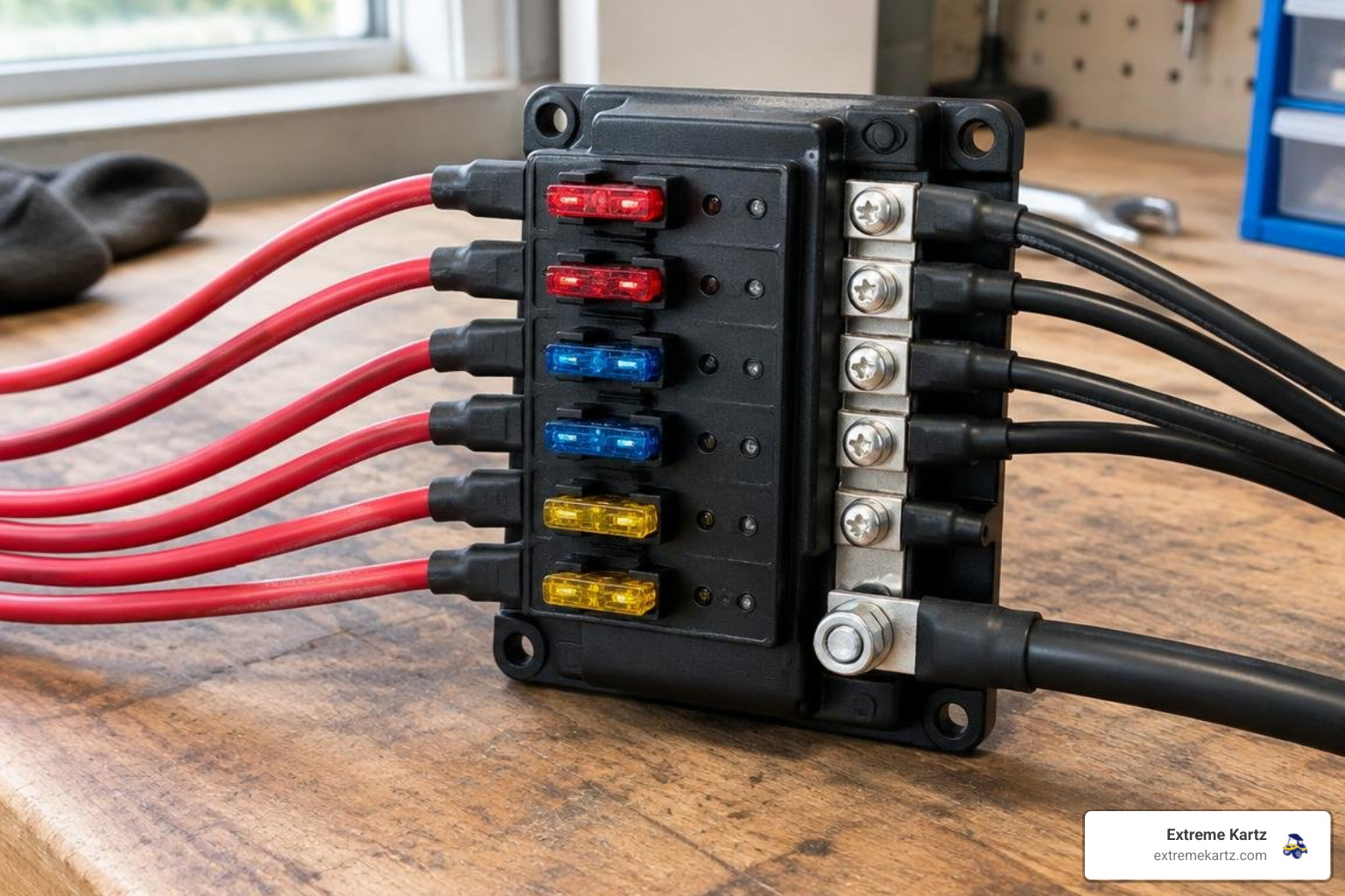
Sizing Components for Golf Cart Fuse Box & 12V Accessory Wiring
Proper sizing requires tallying every accessory's continuous amp draw and applying a 1.5x engineering safety margin to ensure your converter and wiring never run at maximum thermal limits.
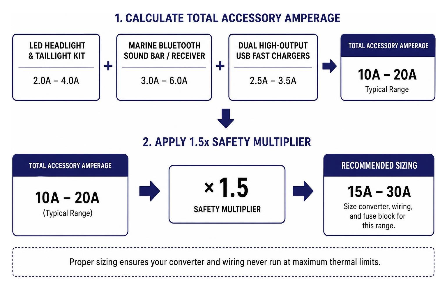
1. Calculating Total Accessory Amperage
Most golf cart owners fall within the 10A to 20A range:
- LED Headlight & Taillight Kit: 2.0A – 4.0A
- Marine Bluetooth Sound Bar / Receiver: 3.0A – 6.0A
- Dual High-Output USB Fast Chargers: 2.5A – 3.5A
- Standard 12V Horn: 1.5A – 3.0A (intermittent)
- High-Output Auxiliary LED Light Bar: 6.0A – 12.0A
A standard lighting, stereo, and USB setup totals roughly 8A continuous draw. Applying our 1.5x safety factor ($8\text{A} \times 1.5 = 12\text{A}$) means a 20A or 30A converter provides reliable, cool operation with plenty of room for future upgrades.
2. Wire Gauge Selection (AWG)
Selecting the proper American Wire Gauge (AWG) prevents resistive voltage drops and wire overheating:
- Main 12V Feed (Reducer to Fuse Block): 10 AWG (rated up to 30A)
- High-Draw Branch Circuits (Light Bars, Multi-Speaker Audio): 12 AWG to 14 AWG (15A–20A fuses)
- Standard Branch Circuits (LED Headlights, Horns): 14 AWG to 16 AWG (10A–15A fuses)
- Low-Draw Branch Circuits (USB Ports, Dome Lights, Gauges): 16 AWG to 18 AWG (5A–7.5A fuses)
Always use marine-grade, tinned copper stranded wire. Tinned copper resists moisture corrosion and withstands constant chassis vibration far better than standard automotive copper wire.
3. Matching ATC/ATO Blade Fuse Sizes
Fuses protect the wiring, not the connected accessory. Size your standard ATC/ATO automotive blade fuses so that the fuse blows before the wire's current rating is exceeded:
- 5A Fuse: Digital gauges, LED accent backlights
- 7.5A Fuse: Dual USB charging sockets
- 10A Fuse: 12V DC power points, basic LED headlight sets
- 15A Fuse: High-draw light kits, standard horns
- 20A Fuse: Amplified sound bars, subwoofers
- 30A Fuse: Main 12V positive feed line from the reducer
Step-by-Step Installation of Golf Cart Fuse Box & 12V Accessory Wiring
Follow these steps for a clean, professional install:
Step 1: Disconnect High Voltage and Ensure Safety
Park the cart on a level surface, engage the parking brake, and turn the key switch OFF. If equipped with a TOW/RUN switch (common on Club Car Precedent/Onward, EZGO TXT48/RXV, and Yamaha Drive models), switch it to TOW. Disconnect the main negative traction battery pack cable, followed by the main positive cable.
Step 2: Mount the Switching DC-DC Converter
Mount the converter to an aluminum chassis plate or structural crossmember in a well-ventilated area away from road debris and direct tire spray. The metal chassis acts as an additional heat sink.
Step 3: Wire the High-Voltage Input Side
- Connect the converter's high-voltage negative input wire directly to the main traction battery pack negative terminal (or the dedicated negative controller/BMS bus bar).
- Install a waterproof inline fuse holder (using a 5A–10A high-voltage rated fuse) within 6 inches of the main battery positive terminal. Connect the converter's constant positive input wire to this fused terminal.
- For 5-wire converters featuring a switched key trigger wire, route the trigger lead to the cold (switched) terminal of the key switch or the output side of your solenoid. This ensures the converter powers down when the key is turned off, eliminating parasitic drain.
Step 4: Mount and Wire the Central Fuse Block
Mount your marine-grade blade fuse block in an accessible location under the seat or behind the front dash access cover.
- Run a 10 AWG red wire from the converter's 12V positive (+) output to the central positive input stud on the fuse block.
- Run a 10 AWG black wire from the converter's 12V negative (-) output to the fuse block's integrated negative ground bus bar.
Step 5: Route and Connect 12V Branch Accessories
Run dedicated positive and ground wire pairs from the fuse block out to each individual accessory:
- Route wiring cleanly through protective split-loom tubing, securing harnesses to the chassis every 12 to 18 inches with UV-rated zip ties.
- Wire your EZGO Light Kits or aftermarket headlights to an individual fuse slot (e.g., 15A), routing the positive feed through your dash-mounted rocker switch.
- Wire your Club Car Radio Speakers and stereo deck. If the stereo requires memory retention, connect the yellow memory lead to a constant 12V output and the red power lead to a switched fuse block terminal.
- Use adhesive-lined heat-shrink butt connectors and ring terminals to make waterproof, vibration-proof terminations.
Step 6: Verify and Power Up
Recheck all polarity connections with a digital multimeter before installing any fuses. Once verified, reconnect the main battery pack terminals, flip the switch from TOW to RUN, insert your blade fuses one by one, and test each accessory circuit.
Resolving the Club Car OBC Relay and Lithium Battery Considerations
Installing 12V wiring on specific cart platforms requires accounting for factory charging interlocks and modern lithium conversions.
The Club Car On-Board Computer (OBC) Workaround
Club Car DS and Precedent models built from roughly 1995 through 2014 utilize an On-Board Computer (OBC). The OBC monitors energy entering and exiting the battery pack via a negative cable routed through an internal sensing coil (the OBC "donut").
If you connect a voltage reducer's ground wire directly to the battery negative post instead of routing through the OBC or connecting to the controller's B- terminal, the OBC fails to track accessory draw. It may misinterpret this unmonitored draw as a parasitic fault, causing the factory charger to shut down prematurely.
To resolve this on OBC-equipped carts:
- Connect the converter's high-voltage ground lead to the controller side of the OBC (the main B- terminal of the speed controller or solenoid ground post), never directly to the battery pack terminal before the OBC sensor.
- If using a basic 4-wire converter that remains energized full-time, wire a 48V coil relay into the key-switch circuit to isolate the converter when the key is off.
Lithium Battery Conversions
When converting a cart to lithium—such as a Bolt Energy, Eco Battery, Lithium Rhino, or Bedrock Battery setup—the factory OBC is typically removed and bypassed entirely. Follow the battery manufacturer's instructions for OBC bypass, CAN connections, and reducer power points.
Keep these best practices in mind for lithium 12V wiring:
- Connect the converter directly to the master terminals of your lithium battery pack or the manufacturer-provided power distribution block.
- When stacking ring terminals on lithium battery posts, always stack largest to smallest, placing high-current controller cables closest to the terminal face.
- For verified schematics on high-output packs, reference manufacturer wiring guidelines from approved lithium providers such as Eco Battery. Extreme Kartz has a certified lithium technician on staff ready to help with fitment and setup questions.
OEM and Aftermarket Golf Cart Fuse Box Locations by Brand
Locating existing fuses or selecting the best spot for your new aftermarket fuse box varies across manufacturers.
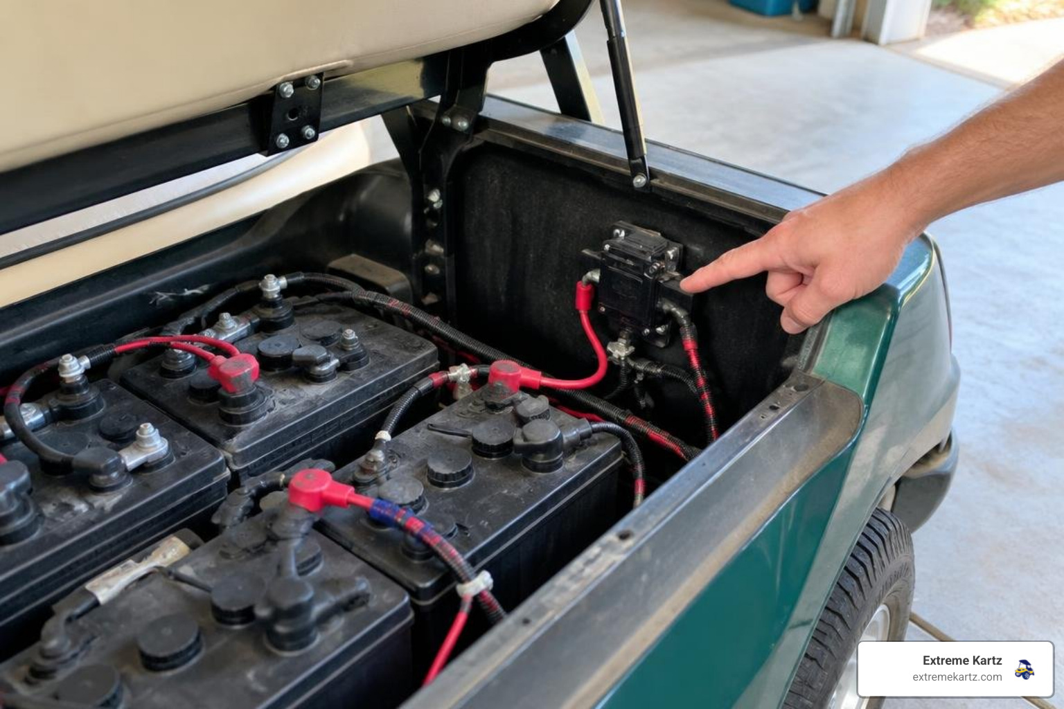
Club Car Fuse Locations
- Club Car DS (Electric & Gas): Electric models typically feature a main 3/8A or 10A glass or ATC fuse located inside the central electrical component box ("black box") between the batteries under the seat. Gas DS models place an inline 10A glass fuse near the starter/generator solenoid.
- Club Car Precedent & Onward: Precedent and Onward models house key fuses under the front seat on the passenger-side bulkhead. You will find an inline 15A mini blade fuse protecting the key switch and charge receptacle circuit. Factory light packages route through an inline harness fuse located beneath the front cowl or tucked behind the center cup-holder dash assembly.
- Club Car Tempo: Tempo models with factory 48V-to-12V converters position an auxiliary 15A blade fuse inside a sealed automotive-style holder mounted to the aluminum chassis frame beneath the central electronics cover.
Upgrading your dash layout? Check our What Model and Year Is My Club Car Golf Cart resource. Prices and dimensions are accurate as of publish; confirm exact specs on each product page:
- Dash Assembly, Club Car Carbon Fiber Precedent 2004-07 ($274.95)
- Dash Assembly, Club Car Precedent/Onward/Tempo Carbon Fiber 2008.5-Up ($209.95)
- DoubleTake Sentry Storage Dash for Club Car Precedent 04+ ($209.95) — a direct-fit storage dash for the factory Club Car Precedent (2004 and up)
- Dash Assembly, Club Car 1982-Up DS Carbon Fiber ($199.95)
- Dash Assembly, Club Car 1982-Up DS Regal Burl ($209.95)
- Key Switch, Club Car Gas 1983.5–95 ($63.95)
EZGO Fuse Locations
- EZGO TXT (1996–present): The TXT (which remains in active production) positions the primary 48V/36V control circuit fuse (typically 10A or 15A blade type) adjacent to the main solenoid on the central passenger-side battery wall. Factory 12V lighting harnesses include an inline fuse holder under the driver-side front cowl area or beneath the seat near the battery charger port.
- EZGO RXV: The RXV utilizes a sensitive AC drive system. Fuses reside under the rear plastic controller cover/splash shield directly behind the battery pack. You will find a 10A main control fuse and a 7.5A auxiliary circuit fuse. Never tap directly into RXV controller harness wires. Always run 12V accessories from a dedicated voltage reducer connected straight to the main pack terminals.
For dash upgrades and replacement parts, browse our EZGO TXT Parts Accessories collection, including:
- Dash Assembly, EZGO 1994-Up Medalist/TXT Carbon Fiber ($219.95)
- EZGO Carbon Fiber Side Trim ($139.95)
- Radio-ready RXV Carbon Fiber Elite Dash ($399.95)
- Radio-ready EZGO TXT Elite Dash in Greywood ($444.95)
Yamaha Fuse Locations
- Yamaha G29 / Drive & Drive2: Yamaha electric carts place the primary 12V auxiliary and control fuses inside the battery compartment on the passenger-side frame rail. Most factory harnesses include an inline 25A yellow ATO fuse protecting the main accessory lead, along with a 10A mini-fuse dedicated to the DC power receptacle.
- Gas Models: Gas Drive and Drive2 models locate a multi-fuse rubber holder containing 10A and 20A blade fuses mounted to the engine bay bracket next to the starter solenoid.
Identify your model using our guide on What Model and Year Is My Yamaha Golf Cart, or explore our complete catalog of Yamaha Golf Accessories.
Troubleshooting Blown Fuses and Wiring Faults
A blown fuse is a safety feature doing its job—it sacrifices itself to protect your wiring from melting and catching fire. When an electrical fault occurs, follow a structured diagnostic process.
How to Test Blown Fuses with a Multimeter
While you can sometimes spot a melted filament through the transparent plastic housing of an ATC/ATO blade fuse, hairline fractures often hide from plain sight. Testing with a digital multimeter takes less than two minutes and provides 100% certainty:
- Set Up the Meter: Turn your digital multimeter dial to the Continuity setting (marked with an audio wave icon) or lowest Resistance ($\Omega$) setting.
- Establish a Baseline: Touch the black and red probe tips together. The meter should beep continuously and display $0.0\text{ }\Omega$ (zero resistance).
-
Test the Fuse: Touch the probe tips to the two exposed metal test tabs on the back of the blade fuse (you do not even need to pull the fuse from the block).
- Good Fuse: Meter beeps and displays near $0.0\text{ }\Omega$ to $0.2\text{ }\Omega$.
- Blown Fuse: Meter remains silent and shows O.L. (Open Loop / Infinite Resistance).
A replacement fuse costs just $1 to $5, while a professional shop diagnosis for an untraced short circuit can easily run $100 to $300. Keep a multi-amp blade fuse assortment in your glove box.
Diagnosing Shorts to Ground and Overloaded Circuits
If a replacement fuse blows immediately upon insertion or as soon as you flip an accessory switch, do not insert a higher-amp fuse. Installing a 30A fuse into a circuit designed for 10A turns your wiring into the weakest link, leading to melted harnesses and fire risks.
Diagnose the root cause using this systematic check:
- Inspect Rub Points Along the Chassis: Golf cart frames flex during operation. Inspect where wire harnesses pass through aluminum seat brackets, steering column cowls, and suspension mounting plates. Look for pinched wires or worn insulation creating a direct short to ground.
- Check Marine Switch Terminals & Connectors: Road spray and moisture can corrode the rear terminals of dash toggle switches. Replace compromised spade connectors with heat-shrink, adhesive-lined terminals.
- Isolate Individual Accessories: Disconnect every accessory powered by that specific fuse circuit. Replace the fuse. Reconnect accessories one at a time until the fuse blows. The last connected device is the faulty unit containing an internal short.
- Inspect Voltage Reducer Ground Isolation: Confirm that your 12V negative return paths route cleanly to the isolated negative terminal on your fuse block, rather than grounding directly into an aluminum chassis member that shares a high-voltage motor return.
For street-legal turn signal kits and lighting issues, review our dedicated guide on Golf Cart Turn Signal Kit upgrades.
Frequently Asked Questions About Golf Cart Fuse Boxes and 12V Accessories
Can I wire 12V LED lights directly to a 36V or 48V battery pack?
No. Connecting 12V-rated LED lights directly to a 36V or 48V pack will instantly destroy the internal LED driver boards and melt the housings due to severe overvoltage. You must step down the pack voltage to 12V using a switching DC-DC converter.
Note: MadJax Ultimate Plus light kits are real, cart-specific products for models including Precedent, RXV, TXT, and Drive. They include a built-in voltage reducer, operate on 12–48V systems, and do not require a separate converter. For example, the Club Car Precedent MadJax Ultimate Plus kit lists high/low-beam headlights, daytime running lights, self-canceling turn signals, a mechanical brake switch with timer, and dual USB ports, but does not list a horn. The Ultimate upgrade kit for Precedent, RXV, and Drive/G29 is not a light kit and contains no lights; it adds a turn signal switch, steering column cover, brake switch, and horn to an existing MadJax basic light kit. DoubleTake Spartan, Titan, Phantom, and Phoenix light packages are real, body-kit-specific packages and are required accessories for DoubleTake body kits, not standalone light kits for factory-body carts.
Why does my golf cart accessory fuse blow as soon as I turn on the switch?
A fuse that blows the exact instant a switch is toggled indicates a hard short to ground. This typically occurs when a positive supply wire has rubbed through its insulation against a metal chassis component, when switch terminals are wired backward (sending positive 12V directly into a ground terminal), or when an accessory has suffered internal electrical failure.
How do I wire my 12V fuse block so accessories turn off with the key?
To prevent accessories from draining your battery pack when the cart is parked, use a 5-wire switching voltage reducer that includes an integrated ignition trigger wire (typically thin green or yellow). Connect this trigger wire to the switched side of your cart's key switch.
If your voltage reducer only features 4 wires (main input positive/negative and 12V output positive/negative), install a heavy-duty 48V continuous-duty relay on the high-voltage input line, using the key switch to energize the relay coil.
Conclusion
Building a clean, safe, and reliable 12V accessory network on your golf cart comes down to three core rules: use a high-efficiency switching DC-DC converter across the entire battery bank, protect every branch circuit with a properly sized marine-grade fuse block, and use quality tinned copper wire with waterproof heat-shrink connections.
Taking the time to wire your accessories properly protects your battery pack, eliminates mysterious electrical shorts, and ensures that your lights, sound system, and electronics work flawlessly on every ride.
Need help sizing the right voltage reducer, selecting an LED harness, or building out your electrical system? We offer free ground shipping on orders over $100 within the continental United States, with a published handling time of 1–3 business days and typical transit times of 3–7 business days.
Explore our full lineup of premium golf cart accessories, browse our complete voltage-reducers collection, or contact our technical team at Extreme Kartz today for personalized fitment guidance on your build.


