


The Easiest Way to Understand Your Golf Cart Battery Wiring Diagram
A Simple Golf Cart Battery Wiring Diagram Starts With Series Wiring

A golf cart battery wiring diagram shows how individual batteries connect to create the cart's full system voltage. In most 36V and 48V carts, batteries are wired in series: connect the positive terminal of one battery to the negative terminal of the next, then use the two open end terminals as the pack's main positive and main negative connections.
| Cart system | Common battery setup | Wiring method |
|---|---|---|
| 36V | Six 6V batteries | Series |
| 48V | Six 8V, eight 6V, or four 12V batteries | Series |
| 72V | Six 12V batteries | Series |
Series wiring adds voltage while keeping the amp-hour capacity of one battery. Parallel wiring does the opposite: it keeps voltage the same and adds capacity. That distinction matters because a single misplaced cable can cause no-power problems, damaged components, or a dangerous short.
The physical battery layout, cable routes, charger connections, solenoid wiring, and controller leads can vary by model. Always match the diagram to your cart's exact make, model, year, battery voltage, and battery type before moving a cable.
I'm Martin Davis, owner of Extreme Kartz, where I work with technicians and manufacturers to help cart owners make confident upgrades, including lithium conversions and electrical-system planning. In this guide, I will break down each part of a golf cart battery wiring diagram in plain language so you can understand what belongs where before you begin.

Fundamentals of Reading a Golf Cart Battery Wiring Diagram
Understanding a golf cart battery wiring diagram comes down to recognizing how power flows through a high-current circuit. Deep-cycle lead-acid golf cart battery packs rely almost exclusively on series connections to step up output potential to the 36-volt, 48-volt, or 72-volt thresholds required by current electric traction motors.
When batteries connect positive-to-negative down the line, system voltage stacks cumulatively. For instance, linking six 8-volt batteries in series yields a total resting nominal output of 48 volts. However, the total capacity - measured in amp-hours (Ah) - remains equal to that of a single battery unit. If you instead link batteries in parallel (positive to positive, negative to negative), system voltage stays at 8 volts while total runtime capacity accumulates. Because electric golf cart motor controllers require elevated operational potential to drive current efficiently without creating excess electrical resistance, series wiring serves as the core foundation for traditional lead-acid battery banks.

To follow a standard wiring schematic, you need to understand the main power paths and components that connect to the battery tray:
- Jumper Cables: Heavy-gauge interconnecting cables that form the series links between individual battery terminals. Every series-connected battery pack uses exactly one fewer jumper cable than the total number of physical batteries in the tray (e.g., a six-battery pack uses five jumpers, while an eight-battery bank uses seven).
- Main Positive Terminal: The sole unlinked positive battery post at the start of the series chain. This high-current connection feeds directly into the primary terminal of the main solenoid.
- Main Negative Terminal: The sole unlinked negative battery post at the terminus of the series chain. This heavy cable runs directly to the motor controller's B- (battery negative) input terminal or the main electrical grounding block.
- Traveler Wires: Lighter control logic wires (typically 16 to 18 AWG) attached to key terminals to route voltage to key switches, pedal microswitches, state-of-charge meters, or onboard charger logic circuits.
When working with heavy current draw, cable gauge selection dictates both performance and overall safety. Standard factory equipment from manufacturers like Club Car, EZGO, and Yamaha typically ships with 6 AWG (American Wire Gauge) battery jumper cables. While 6 AWG works for stock golf carts operating under moderate conditions, upgraded performance carts, lifted builds with larger tires, or carts utilizing high-amp speed controllers demand heavier wiring. Upgrading to 4 AWG or 2 AWG cables substantially minimizes voltage drops under load, lowers system operating heat, and delivers crisper throttle response.
When running 12-volt accessories off higher-voltage packs, integrating a dedicated voltage reducer for golf cart setups is vital to prevent severe cell imbalance across your battery bank.
How to Read a Golf Cart Battery Wiring Diagram for 36V and 48V Systems
Reading a diagram requires tracking electrical potential from start to finish. In a typical daisy-chained 36V or 48V system, trace the positive lead from the cart's main solenoid back to the first battery's positive post (+). From that same battery, follow the short interconnecting jumper cable attached to its negative terminal (-); it routes directly to the positive post (+) of battery number two.
This alternating pattern repeats across every battery in the compartment:
- Battery 1 negative (-) to Battery 2 positive (+)
- Battery 2 negative (-) to Battery 3 positive (+)
- Battery 3 negative (-) to Battery 4 positive (+)
- Battery 4 negative (-) to Battery 5 positive (+)
- Battery 5 negative (-) to Battery 6 positive (+)
The final open negative terminal on Battery 6 functions as the system's main negative return. On standard models, this heavy wire feeds to the controller B- post. From the controller and solenoid, supplementary traveler wires distribute operational logic signals to key switches, forward/reverse switches, and charger receptacles. If your cart has been modified, match the wiring layout to the exact cart platform, controller style, charger system, and battery voltage before moving any cable.
Battery Configurations and Cable Sizing
Golf cart manufacturers engineer battery compartments around different battery physical sizes and pack configurations to deliver optimal weight distribution and overall range:
- Six 8V Batteries: The standard 48-volt configuration found in most modern golf carts. It uses five jumper cables and provides a great balance of voltage and amp-hour capacity within a compact footprint.
- Eight 6V Batteries: Offers maximum range and amp-hour storage capacity for 48V systems, but requires seven jumper cables and additional physical tray space under the seat or in the rear bag well.
- Four 12V Batteries: Simplifies installation by reducing terminal connections to just three jumper cables. While easier to wire, 12-volt deep-cycle batteries generally offer lower total reserve capacity than 6V or 8V options.
When securing battery wire lugs to lead post terminals, applying exact mechanical torque is crucial. Loose hardware causes high electrical resistance, resulting in arcing, melted lead posts, and electrical failures. Recommended torque for standard 5/16-inch battery post studs should follow exact manufacturer specifications to ensure a tight connection. Standard Yamaha Drive2 48V manuals specifically call out exact manufacturer torque parameters for terminal leads.

Step-by-Step 48V Golf Cart Setup and Conversion Principles
Before handling battery tools or adjusting heavy cables, strict safety precautions are mandatory. Deep-cycle battery banks store substantial chemical and electrical energy capable of producing severe electrical shorts, structural welding arcs, or personal injury if accidentally shorted.
Always follow these critical pre-work safety measures:
- Toggle the cart's Tow/Run switch to the Tow position to remove power from the motor controller logic board.
- Remove all metal jewelry, wristwatches, and rings that could bridge a live electrical circuit.
- Put on heavy eye protection and insulated safety gloves.
- Use double-insulated hand tools when working directly over battery posts.
- Always disconnect the main negative cable first during disassembly, and reconnect it last upon final assembly to eliminate frame grounding paths.
A 48V wiring layout should always be verified against the cart's exact make, model, year, battery type, and controller configuration. Factory harness routing can vary even when two carts use the same pack voltage.
How to Wire a 48V Golf Cart Battery Wiring Diagram Step-by-Step
Wiring a 48V battery bank logically requires methodical, single-step assembly:
- Position each battery inside the tray so that adjacent positive and negative terminals line up cleanly to keep jumper cable lengths short.
- Install the primary interconnecting jumper cables sequentially between positive and negative posts, keeping nuts loose until all cables sit flat on the post bases.
- Route the main positive cable from the open positive terminal of the first battery directly to the high-current post of the main solenoid.
- Route the main negative cable from the open negative terminal of the final battery in the chain directly to the controller B- terminal or main ground block.
- Tighten all post fasteners securely to proper manufacturer torque specifications using a torque wrench.
- Coat finished terminal connections with dielectric grease or corrosion inhibitor spray.
- Set a digital multimeter to direct current (DC) voltage and measure across the main positive and main negative post terminals. A healthy, fully charged rested 48V lead-acid battery pack should register between 50.5V and 51.2V.
Converting 36V to 48V Systems and Platform Quirks
Converting an older 36-volt cart (such as an EZGO TXT or Medalist) to a 48-volt system involves more than simply dropping extra batteries into the tray. Because system potential increases by 33%, all high-current components must be rated for 48V operation:
- Solenoid Upgrade: Stock 36V solenoids will overheat or fail if energized by a 48V control circuit. Install a continuous-duty 48V heavy-duty solenoid equipped with a properly sized diode and pre-charge resistor.
- Speed Controller: Replace the factory 36V controller with a 48V-compatible or programmable unit capable of handling upgraded voltage and amperage limits.
- Motor Considerations: Stock 36V series motors can handle 48 volts, yielding noticeable increases in top speed and torque, provided thermal operating limits are monitored.
Different cart brands incorporate unique manufacturer quirks when routing battery wiring circuits:
- Club Car (OBC Systems): Precedent and DS models equipped with an On-Board Computer (OBC) route the main negative battery cable through a physical hall-effect sensor hole in the OBC housing before running to the controller B- post. Bypassing or misrouting this wire will prevent the battery charger from functioning properly.
- EZGO (RXV Series): RXV AC-drive carts feature separate controller logic power connections, including a red wire connected to the solenoid B+ terminal and a dedicated controller B- return wire.
- Yamaha (Drive & Drive2): Yamaha systems mandate specific terminal torque parameters and feature distinct main fuse harness configurations located near the main positive battery post.
Wiring Differences Between Lithium Conversions and Lead-Acid Batteries
Modern lithium battery technology (specifically Lithium Iron Phosphate, or LiFePO4) streamlines golf cart battery trays. Traditional lead-acid installations require heavy multi-battery series chains joined by individual jumper cables. In contrast, drop-in single-pack lithium solutions consolidate power generation into a single casing.
When transitioning to a drop-in lithium battery system, the overall wiring process becomes much simpler:
- All inter-battery jumper cables are eliminated completely.
- A single main positive lead connects from the lithium battery module to the solenoid.
- A single main negative lead connects directly to the controller B- post.
- System cell balancing, low-voltage protection, and thermal monitoring are handled internally by an integrated Battery Management System (BMS).
For modular drop-in lithium systems operating in parallel, modules connect positive-to-positive and negative-to-negative across a central busbar. The specific layout should follow the battery manufacturer's installation instructions and the cart's controller requirements.
When evaluating high-performance lithium conversions for your vehicle, we recommend sticking with established, high-quality brands like Bolt Energy, Eco Battery, Lithium Rhino, and Bedrock Battery, all of which you can shop in our golf cart lithium batteries collection.

Wiring Accessories Without Damaging Your Battery Bank
One of the most common electrical mistakes golf cart owners make is tapping 12-volt accessories (such as lights, stereos, or USB chargers) directly across two 6-volt or one 12-volt battery within a 48V series pack. Direct tapping creates severe voltage imbalances across individual cells. The batteries supplying the accessory draw down faster than the rest of the bank, causing premature battery failure and reduced overall vehicle performance.
To supply 12-volt power safely across a 36V or 48V golf cart system:
- Install a dedicated voltage reducer (voltage converter) that pulls power evenly across the entire 36V or 48V pack and steps it down to a stable 12V output.
- Connect the reducer's high-voltage input leads directly across the main positive and main negative terminals of the entire battery bank.
- Run accessory lighting, horn circuits, and audio equipment off the 12-volt output side of the reducer through a fused distribution block.
For detailed accessory upgrade advice, explore our comprehensive guides on selecting a golf cart light kit, reviewing the golf cart stereo ultimate guide 2026, or planning custom dash builds in the golf cart dashboard ultimate guide 2026.
Troubleshooting Common Golf Cart Electrical and Terminal Connections
When a golf cart fails to operate or experiences power cutouts under acceleration, systematic multimeter troubleshooting helps isolate whether the fault stems from battery pack connections, solenoids, or speed controllers. Use the cart's exact service documentation for vehicle-specific wire colors, harness routing, and controller terminal identification before testing or moving any wires.
| Symptom | Probable Cause | Diagnostic & Solution |
|---|---|---|
| Cart is dead; no power to lights or key switch | Open main fuse, loose main negative, or pack below threshold | Check total pack voltage with multimeter. If below ~40V (on 48V system), charger won't engage. Inspect main battery cables and fuses. |
| Solenoid does not click when pedal is depressed | Blown microswitch, faulty key switch, or active charger interlock | Test for switched 48V signal at solenoid coil terminals. Verify charger handle is disconnected from charger port. |
| Cart hesitates or cuts out under heavy acceleration | High voltage drop due to corroded lugs or loose post nuts | Perform a load voltage drop test across heavy gauge cables. Replace corroded wires showing >0.5V loss under load. |
| Battery charger fails to turn on | OBC interlock failure, broken sense wire, or blown receptacle fuse | Reset Club Car OBC by disconnecting main negative terminal for 10 minutes. Check continuity on gray sense lead. |
Frequently Asked Questions About Golf Cart Wiring
What is the difference between wiring golf cart batteries in series vs. parallel?
Series wiring connects the positive terminal of one battery to the negative terminal of the next battery in line. This configuration stacks the voltage of each battery together while keeping the overall amp-hour (Ah) capacity equal to a single battery. Deep-cycle lead-acid golf cart packs rely on series connections to achieve system operating thresholds of 36V, 48V, or 72V.
Parallel wiring connects all positive terminals together and all negative terminals together. This keeps the voltage constant at the rating of a single battery while combining the total amp-hour capacity. Parallel wiring is primarily used in drop-in lithium battery modules to extend driving range without increasing system voltage.
What gauge wire should I use for golf cart battery jumper cables?
Stock golf carts from the factory typically use 6 AWG (American Wire Gauge) cables for standard duty. However, upgrading to 4 AWG or 2 AWG battery cables is highly recommended for lifted carts, vehicles with upgraded motors or controllers, or carts heavily loaded with passengers. Thicker wire gauge lowers electrical resistance, reduces cable operating heat, minimizes voltage drops under load, and optimizes total current delivery to the motor.
How do I troubleshoot a 48V golf cart that won't turn on or click the solenoid?
Start by measuring overall battery pack voltage across the main positive and main negative terminals using a digital multimeter; a fully charged rested 48V bank should measure between 50.5V and 51.2V. If total voltage drops below approximately 40V, the solenoid logic board may not engage.
Next, inspect all jumper cable connections and main power leads for loose nuts or corrosion. If the battery bank voltage is healthy, check the Tow/Run switch, key switch, directional pedal microswitches, and charger port interlock signals to ensure logic power reaches the solenoid activation coil.
Conclusion
Understanding your golf cart battery wiring diagram is the most effective way to protect your electrical system, prevent costly component failures, and ensure reliable performance out on the trail or course. Whether you are inspecting stock lead-acid jumper connections, diagnosing power cutouts, or converting your cart to high-performance lithium power, following verified circuit logic and proper safety procedures ensures success.
At Extreme Kartz, we simplify golf cart customization and maintenance for enthusiasts and commercial operators alike. Our staff includes a certified lithium technician to ensure your system design, cable routing, and component choices are perfectly matched to your cart's make and model. All product prices and dimensional specifications are accurate as of publish; please confirm exact fitment specs directly on our product pages prior to purchase.
We offer free ground shipping on orders over $100 within the continental United States, with a published handling time of 1–3 business days and typical transit times of 3–7 business days after handling. If you have any fitment questions or need personalized guidance on your next electrical upgrade, reach out to our team through our golf cart accessories collection. We're here to help you get the job done right.
Related Products

Vendor: 2-AWG Heavy Duty Ring Terminal Lithium Battery Cables – Set of 2


Vendor: Eco Battery 48V 105Ah Thru-Hole Bundle - Select your Cart

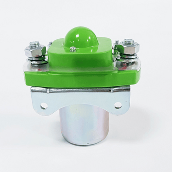
Vendor: 48V/36V VOLT HEAVY DUTY 400+ AMP SOLENOID


Vendor: 6 Way Fuse Block,12V Blade Fuse 6 Circuit ATC/ATO Waterproof Fuse Box Holder with LED Indicator Waterpoof Cover


